

How to install Led Strips on 3D Printers?
In this tutorial you will learn not just that, but also how to make a dimmable led strip for your 3D printer.

Before we begin, how are we going to do this?
There are a few ways of making a control for the led, you will see some of them here:
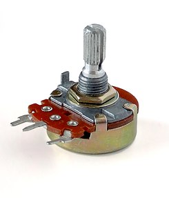
- 1st = This tutorial, current controlled by a potentiometer
- 2nd = The next week bonus tutorial (you will need to sign-up), PWM, controlled by the ramps
- 3rd = PWM controlled by a dedicated electronic circuit or ATTINY (not shown in this tutorial).
First of all, how many leds are you going to use?
- if less than 6 leds (2 rows), you can simply use a 5k potentiometer to control it (METHOD 1)
- up to 2 meters you should use a TIP32 transistor (if more than 50cm, you should use a heatsink) (METHOD)
- up to 6 meters you should use a TIP42 transistor with a heatsink (METHOD 2)
More than 6 meters (or 10amps), you should use the provided driver (if there is) or use a PMW controlled mosfet. but we won’t be doing this since is a bit hard to put 6 meters of leds on a printer.
How to power and cut a led strip?
Its really simple to power it, just plug the + and – to a power source and it will light up. usually 12v. To cut led strip you need to find the “junction”. there is usually one between three leds. (make sure the led strip is working)

GUIDE FOR SMALL STRIPS (METHOD 1 – less than 6 leds)
Here is the schematic:

If you already know a bit about electronics you can follow the schematic above, but if you have no idea of what is that, here is a easier way: follow this image:

(yeah, i know this image sucks, but is the easiest way for someone understand how to connect it)
- The RED lines, are +12v wires. you should power both one side of the LED and one side (left/right) of the potentiometer,
- The BLACK lines are 0V (or GND), you should power ONLY one side (right/left) of the potentiometer,
- The central pin of the potentiometer should go to the (-) / gnd of the led strip.
The potentiometer should be around 1k or 2k. more than this you will have less control (it wont get full brightness)
do not try to power more than 6 leds!, it will BURN/DESTROY the potentiometer!
Also, if you think that your potentiometer is getting hot, smelling bad you can also make the method 2.
GUIDE FOR MORE LEDS! (up to 150 leds) – METHOD 2

First of all, what is a transistor?
Technical description
“A transistor is a semiconductor device used to amplify or switch electronic signals and electrical power. It is composed of semiconductor material with at least three terminals for connection to an external circuit. A voltage or current applied to one pair of the transistor’s terminals changes the current through another pair of terminals. Because the controlled (output) power can be higher than the controlling (input) power, a transistor can amplify a signal”
Understandable description for newbies
The transistor is like a valve, there is a tube with two sides, a collector and a emitter, and on the middle there is a blocking device that with a small amount of force (voltage to the base) you can make a huge amount of water (energy) pass by it. Check the image to help you understand
![]()
What this means for us? well, if we used a potentiometer to power the leds, we would burn it instantly since it is design for low current, so how we solve this? we add a power transistor, this way, its the transistor who will handle the current and not the potentiometer!
Back to the image, the potentiometer would control how much water would flow trough the base, this way the transistor would set the same amount, but a 100, 1000, a million times stronger
LETS BUILD IT
We will need:
- 1x TIP32 or TIP42
- 1x 10K potentiometer or 10k trimpot (trimpot is like mini potentiometer)
- Any amount of 12V led strips
- 1x Soldering iron
- Some cables to connect everything.
*There are TIP32A, TIP32B and TIP32C, same for the TIP42. the letter means the max voltage that it can accept, any of the three works. buy the cheapest.
How we make it?
First check your transistor pins: you cannot plug it on the wrong side, otherwise it will burn!
the pins are the same for TIP32 and TIP42, but not to other transistors

On the design below, B is for base, C for collector and E for Emitter
Here is the schematic

The image below is easier to understand: The potentiometer pins (right and left) can be inverted, but the middle one must be the signal.
DO NOT PUT + or – IN THE MIDDLE PIN!,

As you can see, the potentiometer still being powered from both sides, but this time, the middle pin (output) is controlling the transistor, which then handle the led strip.
I hope you like your new printer lights !!
Any questions please ask!
Take a look on our other posts for improving your 3DPrinter
The ultimate 3D Printer bed leveling guide
Wow very cool! I will try to light up my 3d printer today. 😀
Hey ,nice post , Been considering lighting up my next 3D printer , useful info , at some point in the future I will be covering the AT tiny processor and it’s uses and will try and remember to link back to this tutorial.
Nice work
A ATTINY could be awesome to control the PMW for the leds, and maybe even control a RGB strip,
Those little chips are extremely powerful.
Wow, really cool. This would look good on my Prusa as it is acrylic! I have some 5050 RGB LED strip lying around could I use those?
HA! COOL! Thanks, I’m gonna start lighting stuff up all around the house now! Can’t wait till next Christmas!!! I’m thinking about lighting my car up now 😉 hehe.